

Whitepaper
Reed Switch Sensor – How to Increase Battery-life by 30% with Low-power Switch Detection
?
Reed Switch Introduction
Reed switches are used in IoT security and smart home applications, including door and window contact sensors and motion detectors. These devices are often powered by low-capacity batteries and coin cells, making high energy efficiency critical. This whitepaper introduces a groundbreaking low-power switch state detection method, allowing developers to increase the battery life of reed and tamper switch applications by 30 percent compared to the traditional approach based on pull-up and pull-down resistors. The new method uses duty-cycled voltage and enables IoT sensors and smart home security products with a longer operational life and battery replacement interval, reducing the costs of ownership and maintenance.
?
About this Whitepaper
Certain IoT applications must continuously monitor the state of a switch while drawing minimal current, and then wake-up and respond to a change in its state. As an example, the microcontroller (MCU) inside a wireless, battery-powered contact security sensor needs to detect a change-of-state event (i.e., a closed door is opened), wake-up (i.e., come out of its low power sleep mode to an active mode), and respond (i.e., send a transmission to a base controller).?
For purposes of this discussion, we can define the MCU energy modes and power consumption as:
- Active Mode: Processor active and code executing, drawing single-digit mA (idle) to dozens of mA (when transmitting)
- Sleep Mode: No code is executing, MCU draws single-digit μA
Traditional methods of switch state detection can result in non-negligible static current draw as shown in Figure 1 Reed Switch with Traditional Switch Detection, resulting in a significant reduction of battery life. This paper proposes a method that can dramatically reduce the switch state detection current draw for certain applications.
?
Known vs. Unknown Predominant Reed Switch State
Traditional Switch State Detection
For contact sensors using traditional mechanical reed switches, switch state detection has typically been implemented using a simple pull-up or pull-down resistor in series with the switch, as shown in Figure 1 Reed Switch with Traditional Switch Detection.
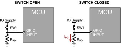
Figure 1 Reed Switch with Traditional Switch Detection
?
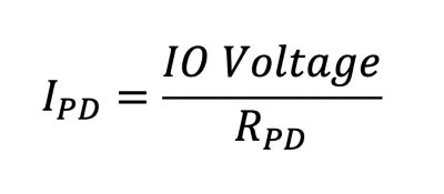
It is readily observable that no current will flow from the IO Supply through the pull-down resistor (RPD) in the SWITCH OPEN case, where-as the SWITCH CLOSED case will cause a static current draw IPD, with:
For example, if RPD = 3 M? and a 3 V IO Supply:
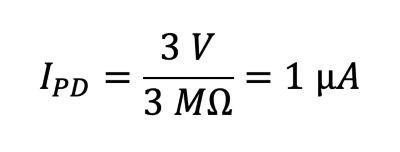
A wireless sensor device may remain in its sleep state > 95% of the time, with the sleep current accounting for up to 75% of the total power consumption over the battery life. So even 1 μA of additional sleep current draw can have a dramatic impact for a wireless sensor battery life.
?
Low Power Switch State Detection
Instead of applying a static IO Voltage to the switch, Low Power Switch Detection employs a duty-cycled excitation voltage. As shown in Figure 2 Reed Switch with Low Power Switch Detection, the GPIO Output applies a pulse-train to one side of switch SW1. The GPIO Input will see the pulse-train output when SW1 is closed, and will simply be grounded through RPD when SW1 is open.
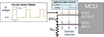
Figure 2 Reed Switch with Low Power Switch Detection
?
The average current through the pull-down resistor in the SWITCH CLOSED case will be dependent on the on-time (TON) and period (TPERIOD) of the pulse-train, and can be calculated as:
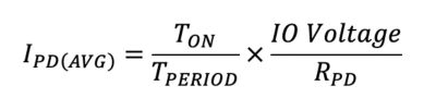
As an example, assuming a pulse-train with a frequency of 10 Hz (TPERIOD = 100 ms) and an on-time of 1 ms, with RPD = 3 M? and IO Supply = 3 V, the average current through the pull-down resistor will be:
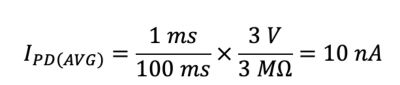
Observe that use of Low Power Switch Detection can achieve a 100x reduction in pull-down resistor current.
?
Reed Switch Implementation Challenges.
While the underlying concept behind Low Power Switch Detection is extremely basic, a practical MCU implementation poses some unique challenges. Specifically, a Low Power Switch Detection implementation must:
- Maintain an excitation pulse-train on its GPIO output while the MCU is in its low power sleep mode. This requirement is fairly straightforward – most MCUs have the ability to output a PWM signal while the processor is in sleep mode.
- Sample its GPIO Input only during the pulse-train on-time intervals to determine the current switch state, without requiring the MCU to exit its sleep mode
- Wake the processor from sleep to active mode only on a change in the switch state
- Support both possible change-of-state events (i.e., switch closed -> switch opened and switch opened -> switch closed)
How to Implement Low Power Switch Detection?
Certain of Silicon Labs’ EFR32 family of Wireless SoC’s support a highly configurable Low Energy Sense (LESENSE) interface, capable of both sensor excitation and data collection even in EFR32’s sleep mode (EM2). LESENSE is available on most EFR32 devices, with the exception of the EFR32xG21 and EFR32xG22.? An in-depth overview of the LESENSE block is outside the scope of this paper (refer to AN0029: Low Energy Sensor Interface), but several LESENSE features that are applicable to a Low Power Switch Detection implementation include:
- Ability to generate a user-programmable excitation pulse-train output while the EFR32 is in EM2.
- Ability to accept the output EFR32’s Analog Comparator (ACMP) as an input
- Ability to coordinate the sampling of the input with the output excitation pulse-train
In this example implementation, the details of the Low Energy Sense (LESENSE) Configuration are as follows:
- In order to minimize power consumption, the LESENSE block is configured to be clocked by the Ultra-Low Frequency RC Oscillator (ULFRCO), an internal 1000 Hz oscillator.
- The LESENSE output excitation pulse-train duration (TON) is configured to be 1 ms and the frequency (1/TPERIOD) is configured to be 10 Hz.
- The LESENSE excitation output is routed (via the LESENSE Channel assignments) to the GPIO Output pin, which is connected externally to one side of the SW1 switch.
- The LESENSE is configured to power up the analog comparator (ACMP) during its excitation phase
- The LESENSE is configured to generate a wake-up IRQ to the core when certain conditions are met
In this example implementation, the Analog Comparator (ACMP) Configuration Details are as follows:
- The ACMP is configured to be powered down outside of sample intervals to minimize power consumption (via the LESENSE)
- The Analog Comparator positive input is connected internally (via a flexible analog port bus) to the GPIO Input and externally to the other side of the SW1 switch
- The Analog Comparator negative input is connected internally to a programmable reference voltage, configured in this example to be a divided version of the IO Supply Voltage
- The Analog Comparator output is configured to generate a wakeup interrupt (IRQ) to the processor
- The Analog Comparator output may be inverted by firmware (using the ACMP1INV bit)
Closed-to-Open Detection
A detailed block diagram of this Low Power Switch Detection implementation on the EFR32 is shown in Figure 3 Low Power Switch Detection on EFR32 – Closed-to-Open Transition
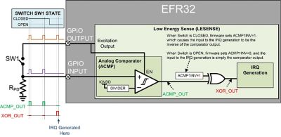
Figure 3 Reed Switch Low Power Switch Detection on EFR32 – Closed-to-Open Transition
?
During the excitation pulse on-times, the LESENSE block will power up the analog comparator and enable its output [DN1]?(ACMP_OUT) to be routed to internal configurable logic.? As shown in Figure 3, the analog comparator output (ACMP_OUT) tracks the GPIO excitation output during the sample intervals while the switch is in the closed position.? However, when the switch opens, the GPIO Input is pulled low and ACMP_OUT will be low during the next sample interval.? With the analog comparator output inversion control bit (ACMP1INV) set, a low on ACMP_OUT during this sample interval causes a high pulse at XOR_OUT, resulting in generation of a wakeup IRQ.
?
Open-to-Closed Detection
A detailed block diagram of Open-to-Closed detection is shown in Figure 4
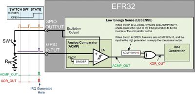
Figure 4 Reed Switch Low Power Switch Detection on EFR32 - Open to Closed Transition
?
With the switch open, the analog comparator output (ACMP_OUT) will be the inverse of the GPIO excitation output during the sample intervals.? However, once the switch closes, ACMP_OUT will be high the next sample interval.? With the analog comparator output inversion control bit (ACMP1INV) cleared, a high transition on ACMP_OUT causes a high pulse at XOR_OUT, resulting in generation of a wakeup IRQ.
?
Initial Switch State Detection
Because the initial state of the switch is unknown at the time the MCU powers on, the firmware example must first determine the switch state before entering the Low Power Switch Detection routine.? The initial state is determined by simply driving the GPIO Output high and reading the state on the GPIO Input pin.
Once the initial state is known, the ACMP1INV bit can be set appropriately to ensure the Low Power Switch Detection is configured to detect the correct state change event (i.e., OPEN->CLOSED or CLOSED->OPEN)
?
Firmware Example Flowchart
Figure 5?shows a simplified flowchart of the Low Power Switch Detection Firmware example.
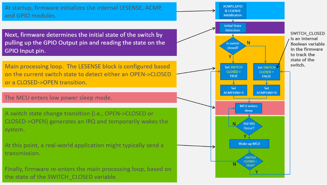
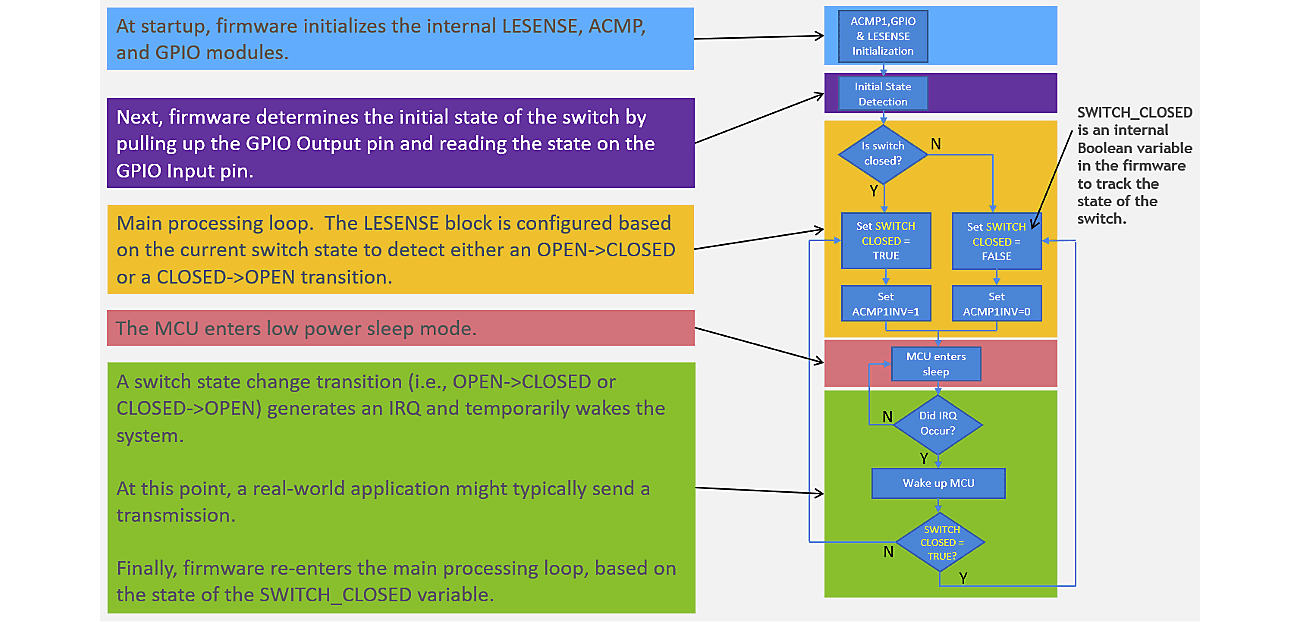
Figure 5 Reed Switch Firmware Example Flowchart
?
Results - Reed Switch Battery Life Comparison
A comparison of the total system current draw on an EFR32FG13 for Traditional vs Low Power Switch Detection is shown in Table 1.? For these measurements, the system is held in a constant state (i.e., either switch state is held closed or switch state is held open). ?“Incremental Current” is the current relative to lowest power state: the Traditional Switch Detection with Switch Opened state.
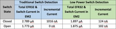
Table 1 Reed Switch Current Measurement Comparison
Other conditions for these measurements:
- DCDC Enabled
- VBATT = IO Supply = 3.0 V
- RPD = 3 M?
Table 2 shows the results of a Zigbee battery life estimator, configured with the following assumptions:
- 0dBm Zigbee Event
- 5.8mA RX, 6mA TX
- Switch Closed 100% of the time

Table 2 Reed Switch Battery Life Comparison Results
?
So this approach can clearly have a significant impact on the overall battery life.
?
Example Code for Reed Switch Low-power Switch Detection
How to get help for implementing low-power switch detection for your reed and tamper switch applications? Our reed switch example code for Silicon Labs EFR32 chipsets gives you a jump start!?
?
Summary
This paper examined the disadvantages of traditional switch detection, and proposed an alternative lower power method to save current in applications where the switch predominant state is unknown, or to allow use of cheaper normally-closed switches for applications where the switch predominant state is known. Finally, an example implementation using the Silicon Labs EFR32FG13 Wireless SoC is described. Silicon Labs offers a range of development tools optimal for developing reed switch sensors. The proposed Low Power Switch Detection implementation is supported by any EFR32 devices that have both LESENSE and ACMP modules - at the moment, this is all EFR32 devices, with the exception of EFR32xG21 and EFR32xG22.?